
TM 5-2410-241-23-3
0216
ASSEMBLY CONTINUED
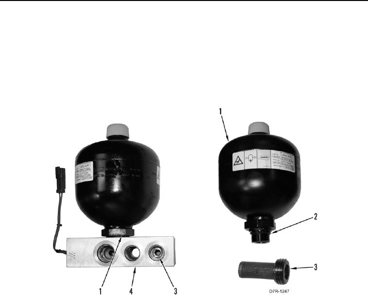
4. Install screen (Figure 19, Item 3) on control manifold (Figure 19, Item 4).
5. Install new O-ring (Figure 19, Item 2) on accumulator (Figure 19, Item 1).
N OT E
If installing new accumulator, refer to Accumulator Charging in this work package.
6. Install accumulator (Figure 19, Item 1) on control manifold (Figure 19, Item 4).
Figure 19. Accumulator.
0216