
TM 5-2410-241-23-3
0216
ASSEMBLY CONTINUED
N OT E
Install O-rings and fittings as noted during disassembly.
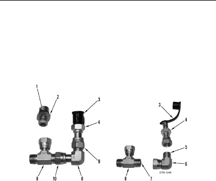
9. Install new O-ring (Figure 21, Item 5) on elbow (Figure 21, Item 6).
10. Install diagnostic port fitting (Figure 21, Item 4) and nut (Figure 21, Item 9) on elbow (Figure 21, Item 6).
11. Install strap and cover (Figure 21, Item 3) on diagnostic port fitting (Figure 21, Item 4).
12. Install new O-ring (Figure 21, Item 7) on T fitting (Figure 21, Item 8).
13. Install elbow (Figure 21, Item 6) and nut (Figure 21, Item 10) on T fitting (Figure 21, Item 8).
14. Install two new O-rings (Figure 21, Item 1) on fitting (Figure 21, Item 2).
Figure 21. Fitting Assembly.
0216