
TM 5-2410-241-23-3
0216
ASSEMBLY CONTINUED
N OT E
Install fittings as noted during disassembly.
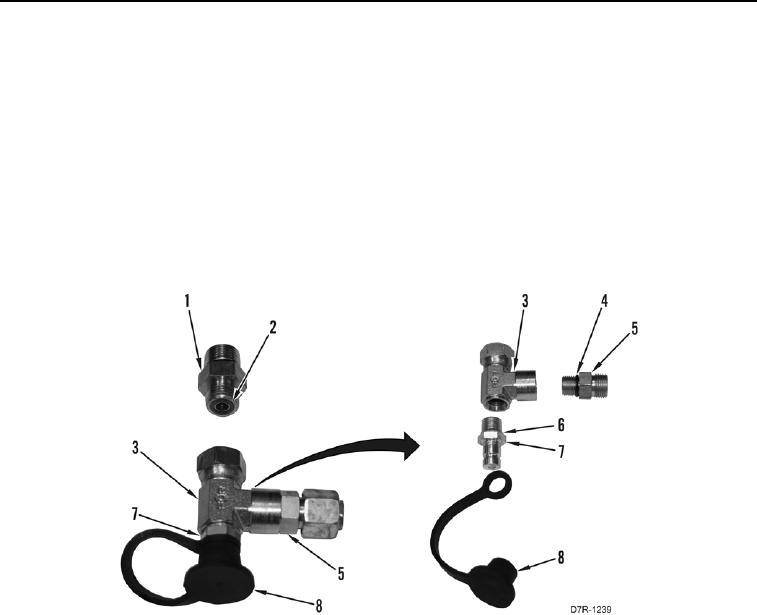
26. Install new O-ring (Figure 27, Item 6) on diagnostic port fitting (Figure 27, Item 7).
27. Install diagnostic port fitting (Figure 27, Item 7) on T fitting (Figure 27, Item 3).
28. Install cover and strap (Figure 27, Item 8) on diagnostic port fitting (Figure 27, Item 7).
29. Install new O-ring (Figure 27, Item 4) on fitting (Figure 27, Item 5).
30. Install two new O-rings (Figure 27, Item 2) on fitting (Figure 27, Item 1).
31. Install fitting (Figure 27, Item 5) on T fitting (Figure 27, Item 3).
Figure 27. Diagnostic Port Fitting Disassembly.
0216