
TM 5-2410-241-23-3
0216
INSTALLATION
000216
N OT E
Remove plugs from all lines, hoses, and tubes.
Install hoses, fittings, and O-rings as noted during removal.
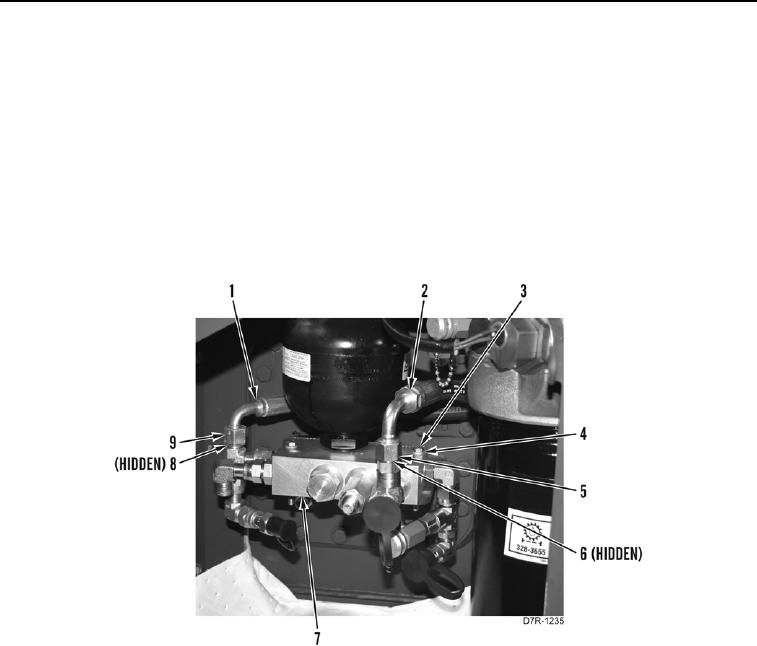
1. Install control manifold (Figure 31, Item 7), two washers (Figure 31, Item 4), and bolts (Figure 31, Item 3) on
machine.
2. Install new O-ring (Figure 31, Item 6), hose (Figure 31, Item 2), and tighten tube nut (Figure 31, Item 5) on
control manifold (Figure 31, Item 7).
3. Install new O-ring (Figure 31, Item 8), hose (Figure 31, Item 1), and tighten tube nut (Figure 31, Item 9) on
control manifold (Figure 31, Item 7).
Figure 31. Control Valve Hoses.
0216