
TM 5-2410-241-23-3
0216
ASSEMBLY CONTINUED
N OT E
Install fittings as noted during disassembly.
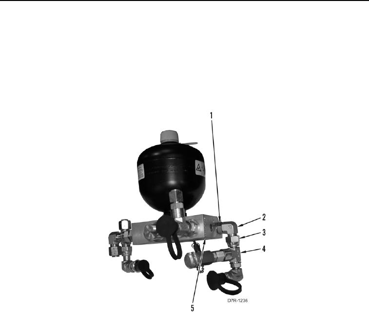
45. Install fitting assembly (Figure 30, Item 2) on control manifold (Figure 30, Item 5) and tighten tube nut
(Figure 30, Item 1).
46. Position T fitting (Figure 30, Item 4) under control manifold (Figure 30, Item 5) and tighten tube nut (Figure 30,
Item 3).
Figure 30. Control Manifold Assembly Sampling Valve and Fitting.
0216
END OF TASK