
TM 5-2410-241-23-3
0216
ASSEMBLY CONTINUED
N OT E
Install fittings and O-rings as noted during disassembly.
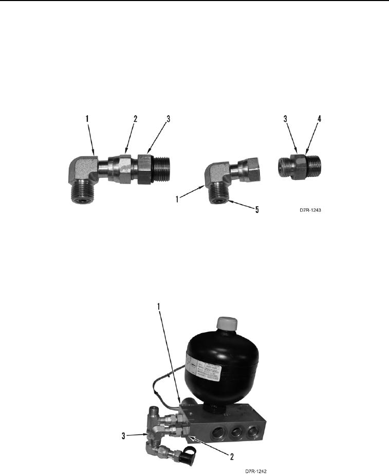
18. Install new O-ring (Figure 23, Item 5) on elbow assembly (Figure 23, Item 1).
19. Install two new O-rings (Figure 23, Item 4) on fitting (Figure 23, Item 3).
20. Install elbow assembly (Figure 23, Item 1) on fitting (Figure 23, Item 3) and tighten tube nut (Figure 23, Item 2).
Figure 23. Elbow Fitting Assembly.
0216
N OT E
Install fittings as noted during disassembly.
21. Install elbow (Figure 24, Item 3) and fitting (Figure 24, Item 2) on control manifold (Figure 24, Item 1).
Figure 24. Control Manifold Assembly Elbow Fitting.
0216