• Home
  • Download PDF
  • Order CD-ROM
  • Order in Print
Figure 31. Control Valve Hoses.
Figure 33. Electrical Connector.

Field Maintenance Manual 3 D7R Dozer Type I With Winch and Type II With Ripper
Page Navigation
  306    307    308    309    310  311  312    313    314    315    316  
img
.
TM 5-2410-241-23-3
0216
INSTALLATION CONTINUED
N OT E
Remove plugs from all lines, hoses, and tubes.
Install line as noted during removal.
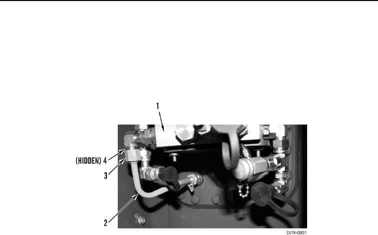
4. Install two new O-rings (Figure 32, Item 4), one line (Figure 32, Item 2), and tighten two tube nuts
(Figure 32, Item 3) on control manifold (Figure 32, Item 1).
Figure 32. Control Valve Line.
0216
0216-28


Privacy Statement
Press Release
Contact

© Copyright Integrated Publishing, Inc.. All Rights Reserved.