• Home
  • Download PDF
  • Order CD-ROM
  • Order in Print
Figure 32. Control Valve Line.
Figure 34. Test Equipment Installation.

Field Maintenance Manual 3 D7R Dozer Type I With Winch and Type II With Ripper
Page Navigation
  307    308    309    310    311  312  313    314    315    316    317  
img
.
TM 5-2410-241-23-3
0216
INSTALLATION CONTINUED
N OT E
Install electrical connections as tagged during removal.
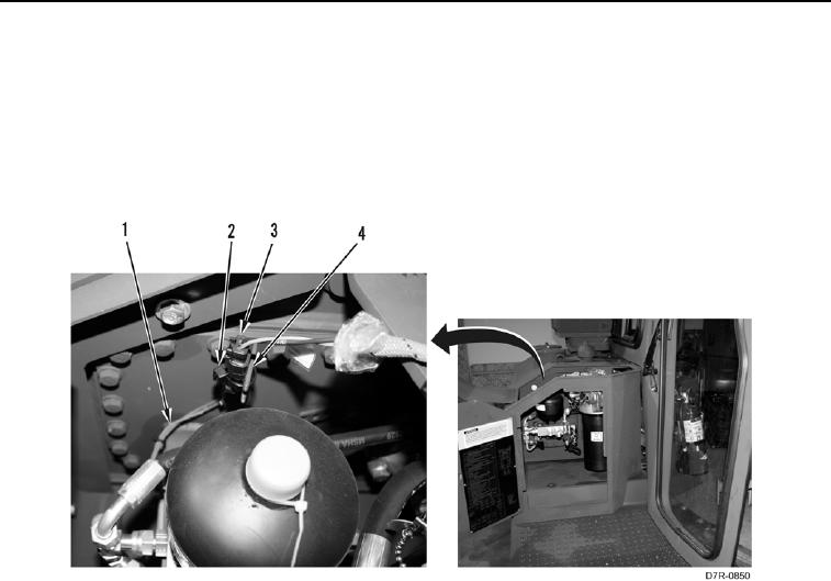
5. Position harness (Figure 33, Item 1) and connect connector (Figure 33, Item 3).
6. Install new tiedown strap (Figure 33, Item 2) on bracket (Figure 33, Item 4) and connector (Figure 33, Item 3).
Figure 33. Electrical Connector.
0216
END OF TASK
0216-29


Privacy Statement
Press Release
Contact

© Copyright Integrated Publishing, Inc.. All Rights Reserved.