
TM 5-2410-241-23-3
0217
REMOVAL
000217
WARN I N G
Contact with oil can damage skin. Wear gloves when handling oil. If oil contacts skin, wash
it off immediately.
Lubricating oil is very slippery. Immedately wipe up any spills. Failure to follow this
i
warning may cause injury.
Failure to follow these warnings may cause injury to personnel.
N OT E
Care must be taken to ensure that fluidsare contained during performance of inspection,
maintenance, testing, adjusting and repair of the product. Be prepared to collect the fluid
with suitable containers before opening any compartment or disassembling any
component containing fluids.
Dispose of all fluids accordingto local regulations and mandates.
Perform disassembly on a clean surface.
Clean exterior of component to prevent contamination.
Cap and plug all lines, hoses and tubesto prevent contamination and leaks.
Tag and mark all hoses and lines to aid installation.
REMOVAL
000217
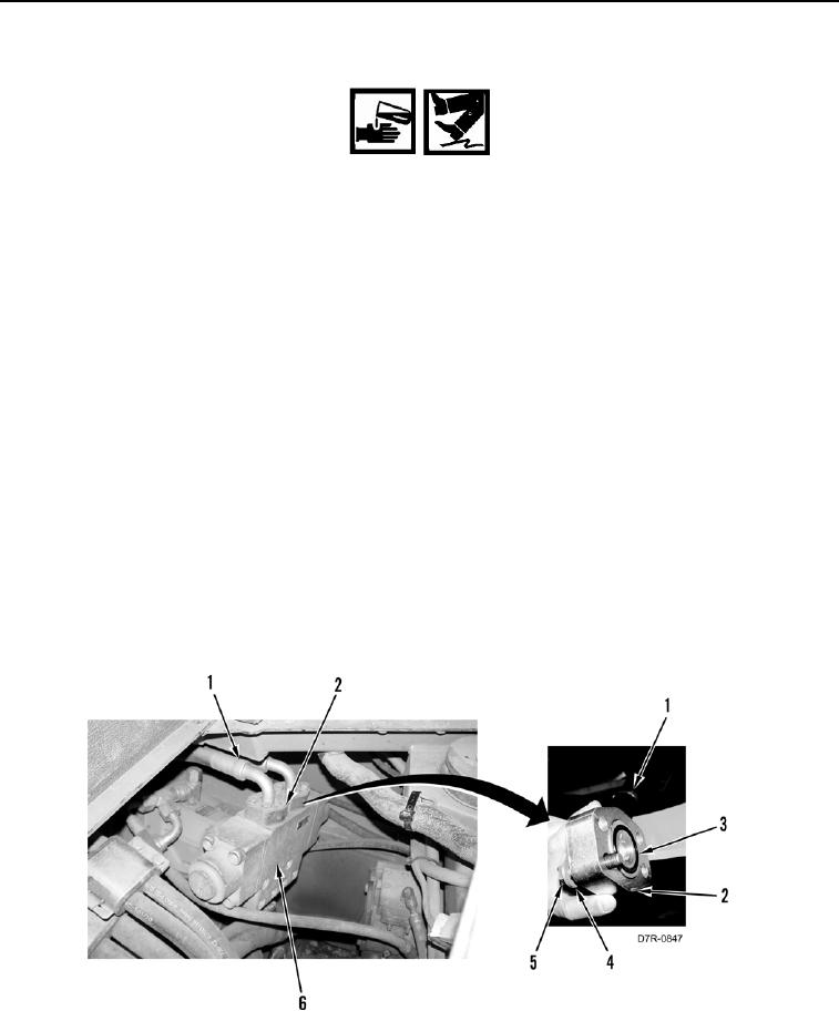
1. Remove eight bolts (Figure 1, Item 5), washers (Figure 1, Item 4), two flanges (Figure 1, Item 2) and hoses
(Figure 1, Item 1) from counterbalance valve (Figure 1, Item 6).
2. Remove two O-rings (Figure 1, Item 3) from hoses (Figure 1, Item 1). Discard O-rings.
Figure 1. Counterbalance Valve.
0217