
6
TM 5-2410-241-23-3
FIELD MAINTENANCE
-
LOWERING EQUIPMENT WITH ENGINE STOPPED
0218
Access Cover Removal, Lowering Equipment Procedure, Access Cover Installation
INITIAL SETUP
Equipment Condition
Tools and Special Tools
0
0
Tool Kit, General Mechanic's
Machine parked (TM 5-2410-241-10)
0
(WP 0302, Item 65)
Drawing Required
0
0
Materials/Parts
TM 5-2410-241-24P, Figure 74
0
0
Rag, Wiping (WP 0303, Item 24)
Estimated Time to Complete
0
0
O-ring (4)
0
1.0 Hr
0
ACCESS COVER REMOVAL
000218
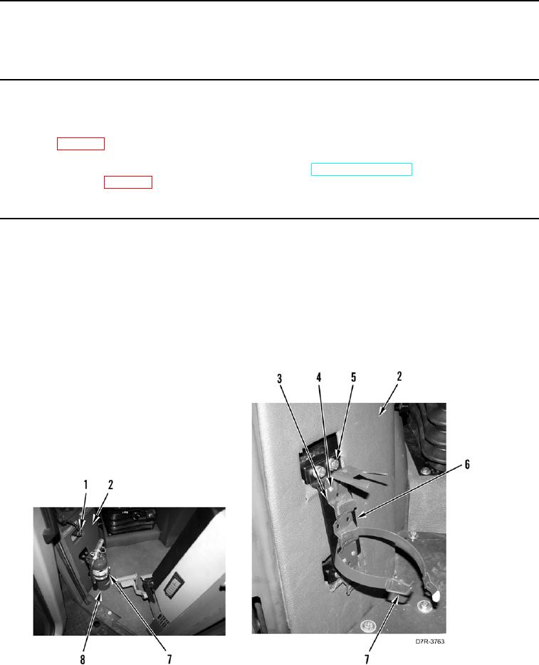
1. Release clasp (Figure 1, Item 7) and remove fire extinguisher (Figure 1, Item 8) from fire extinguisher bracket
(Figure 1, Item 3).
2. Remove four screws (Figure 1, Item 4) and fire extinguisher bracket (Figure 1, Item 3) from mounting bracket
(Figure 1, Item 6).
3. Remove four bolts (Figure 1, Item 5), and mounting bracket (Figure 1, Item 6) from machine.
4. Disconnect messenger module harness connector (Figure 1, Item 1) from machine and position harness
aside.
5. Position trim panel (Figure 1, Item 2) aside.
Figure 1. Fire Extinguisher and Bracket.
0218