
14
TM 5-2410-241-23-3
FIELD MAINTENANCE INSTRUCTIONS
-
BLOWER FAN CASE REPLACEMENT
0219
Temperature Switch Removal, Resistor Removal, Blower Motor Removal, Cleaning and Inspection,
Blower Motor Installation, Resistor Installation, Temperature Switch Installation
INITIAL SETUP
Tools and Special Tools
Equipment Condition
0
0
Tool Kit, General Mechanic's
Machine parked (TM 5-2410-241-10)
0
(WP 0302, Item 65)
0
Instrument panel opened (WP 0262)
0
Materials/Parts
Drawing Required
0
0
Rag, Wiping (WP 0303, Item 24)
0
TM 5-2410-241-24P, Figure 104
0
Tag, Marker (WP 0303, Item 34)
0
Estimated Time to Complete
0
Tiedown Strap (WP 0303, Item 36)
0
3.5 Hr
0
Gasket
0
References
0
0
TEMPERATURE SWITCH REMOVAL
000219
WARN I N G
If CBRN exposure is suspected, personnel wearing protective equipment must handle all
air cleaner media. Contaminated filters must be handled using adequate precautions and
must be disposed of by trained personnel. Consult your CBRN Officer or CBRN NCO for
appropriate handling or disposal procedures. Failure to follow this warning may result in
injury or death to personnel.
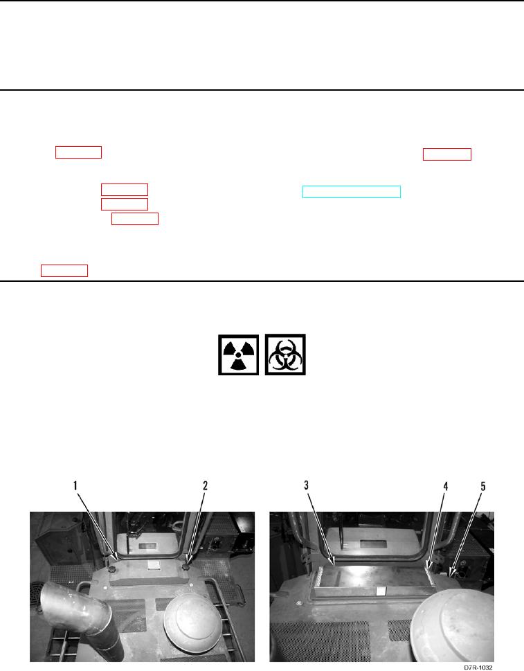
1. Remove two knobs (Figure 1, Item 2), cover (Figure 1, Item 1), plate (Figure 1, Item 3) and cab filter (Figure 1,
Item 4) from platform (Figure 1, Item 5).
Figure 1. Cab Filter.
0219