
TM 5-2410-241-23-3
0219
RESISTOR REMOVAL CONTINUED
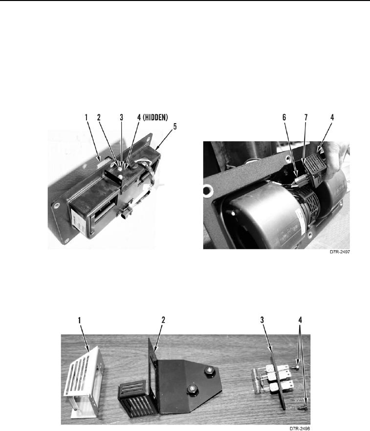
7. Remove two bolts (Figure 5, Item 2), washers (Figure 5, Item 3), plate (Figure 5, Item 4), and guard (Figure 5,
Item 1) from cover (Figure 5, Item 5).
N OT E
Tag connectors to aid installation.
8. Disconnect blower harness connector (Figure 5, Item 6) from resistor (Figure 5, Item 7). Remove resistor and
plate (Figure 5, Item 4) from cover (Figure 5, Item 5).
Figure 5. Resistor Connection.
0219
9. Remove two bolts (Figure 6, Item 4) and resistor (Figure 6, Item 3) from plate (Figure 6, Item 2). Separate
guard (Figure 6, Item 1) from plate.
Figure 6. Resistor.
0219
END OF TASK