
TM 5-2410-241-23-3
0219
RESISTOR REMOVAL
000219
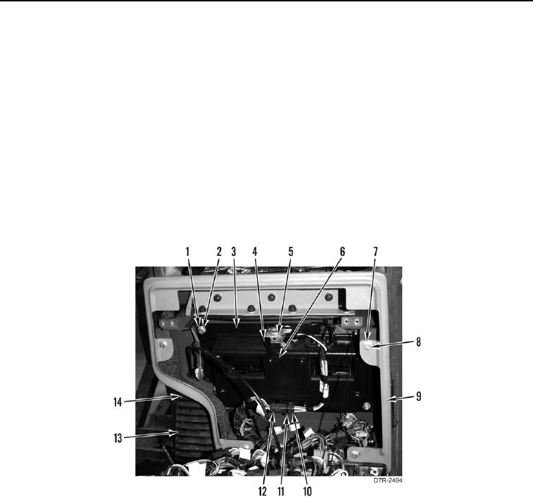
1. Remove four bolts (Figure 4, Item 7), washers (Figure 4, Item 8), and instrument panel enclosure (Figure 4,
Item 9) from machine.
2. Remove two screws (Figure 4, Item 4) and temperature switch (Figure 4, Item 5) from bracket (Figure 4,
Item 6). Set temperature switch (Figure 4, Item 5) aside.
N OT E
Tag connectors to aid installation.
3. Disconnect harness connector (Figure 4, Item 12) from blower harness (Figure 4, Item 10).
4. Remove tiedown strap (Figure 4, Item 11) from blower harness (Figure 4, Item 10). Discard tiedown strap.
5. Remove four bolts (Figure 4, Item 14) and left foot support (Figure 4, Item 13) from machine.
6. Remove six bolts (Figure 4, Item 1), washers (Figure 4, Item 2), and blower motor and cover (Figure 4, Item 3)
from machine.
Figure 4. Blower Motor.
0219