
TM 5-2410-241-23-3
0219
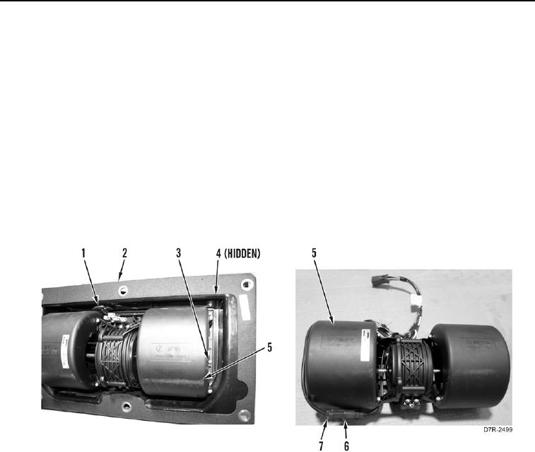
BLOWER MOTOR REMOVAL
000219
1. Remove temperature switch. Refer to Temperature Switch Removal in this work package.
2. Remove resistor. Refer to Resistor Removal in this work package.
3. Remove six bolts (Figure 7, Item 3), three plates (Figure 7, Item 4), and blower motor (Figure 7, Item 5) from
cover (Figure 7, Item 2).
4. Remove blower harness connector (Figure 7, Item 6) from grommet (Figure 7, Item 1) in cover (Figure 7,
Item 2).
5. Remove grommet (Figure 7, Item 1) from cover (Figure 7, Item 2).
N OT E
Tag connectors to aid installation.
6. Disconnect blower motor connector (Figure 7, Item 7) from blower harness connector (Figure 7, Item 6) and
remove harness.
Figure 7. Blower Motor Cover.
0219