
TM 5-2410-241-23-3
0219
TEMPERATURE SWITCH INSTALLATION
000219
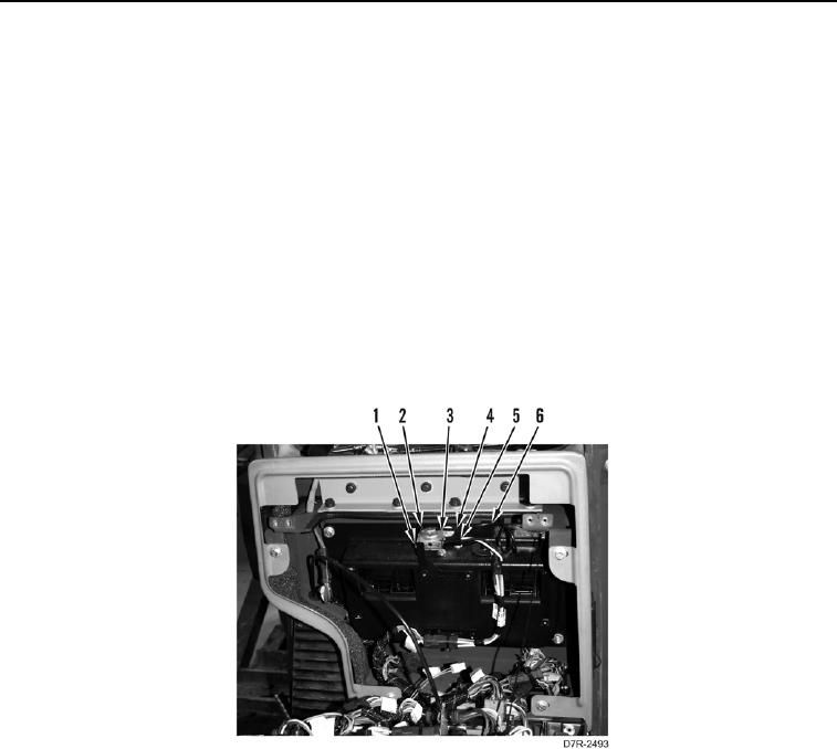
1. Install grommet (Figure 13, Item 6) on machine.
C AU T I O N
Use caution when handling temperature switch tube. The tube is made of a soft metal and
is over 2 feet long. Do not kink or bend tube. Damage to equipment will result.
2. Position temperature switch tube (Figure 13, Item 4) and temperature switch (Figure 13, Item 3) on machine.
3. Install temperature switch tube (Figure 13, Item 4) through frame.
4. Install temperature switch (Figure 13, Item 3) and two bolts (Figure 13, Item 1) on bracket (Figure 13, Item 2).
N OT E
Install connectors as tagged in removal.
5. Connect two blower harness connectors (Figure 13, Item 5) on temperature switch (Figure 13, Item 3).
Figure 13. Temperature Switch.
0219