
TM 5-2410-241-23-3
0219
RESISTOR INSTALLATION CONTINUED
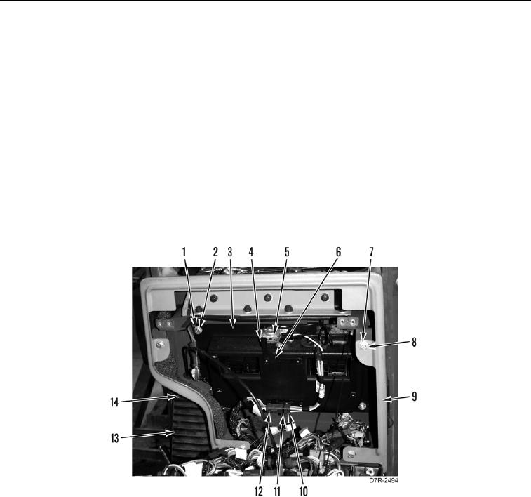
4. Install blower motor and cover (Figure 12, Item 3), six washers (Figure 12, Item 2), and bolts (Figure 12,
Item 1) on machine.
5. Install left foot support (Figure 12, Item 13) and four bolts (Figure 12, Item 14) on machine.
6. Install blower harness (Figure 12, Item 10) and new tiedown strap (Figure 12, Item 11) on cover.
N OT E
Install connectors as tagged in removal.
7. Connect harness connector (Figure 12, Item 12) on blower harness (Figure 12, Item 10).
8. Install temperature switch (Figure 12, Item 5) and two screws (Figure 12, Item 4) on bracket (Figure 12,
Item 6).
9. Install instrument panel enclosure (Figure 12, Item 9), four washers (Figure 12, Item 8), and bolts (Figure 12,
Item 7) on machine.
Figure 12. Blower Motor.
0219
END OF TASK