
TM 5-2410-241-23-3
0219
TEMPERATURE SWITCH INSTALLATION CONTINUED
C AU T I O N
Use caution when handling temperature switch tube. The tube is made of a soft metal and
is over 2 feet long. Do not kink or bend tube. Damage to equipment will result.
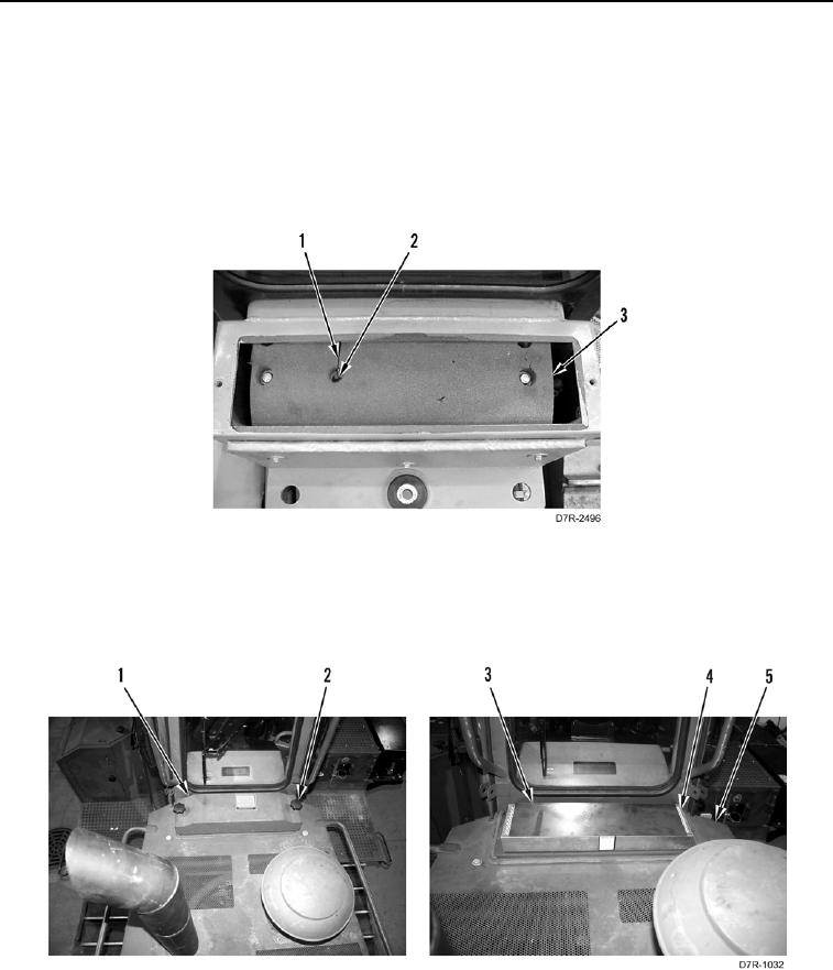
6. Install temperature switch tube (Figure 14, Item 1) through grommet (Figure 14, Item 2) and evaporator coil
(Figure 14, Item 3).
Figure 14. Temperature Switch Tube.
0219
7. Install cab filter (Figure 15, Item 4), plate (Figure 15, Item 3) cover (Figure 15, Item 1), and two knobs
(Figure 15, Item 2) on platform (Figure 15, Item 5).
Figure 15. Cab Filter.
0219
END OF TASK