
TM 5-2410-241-23-3
0217
INSTALLATION CONTINUED
N OT E
Care must be taken to ensure that fluids ae contained during performance of inspection,
r
maintenance, testing, adjusting and repair of the product. Be prepared to collect the fluid
with suitable containers before opening any compartment or disassembling any
component containing fluids.
Remove plugs from lines, hoses, and tubes.
Install hoses and lines as noted during removal.
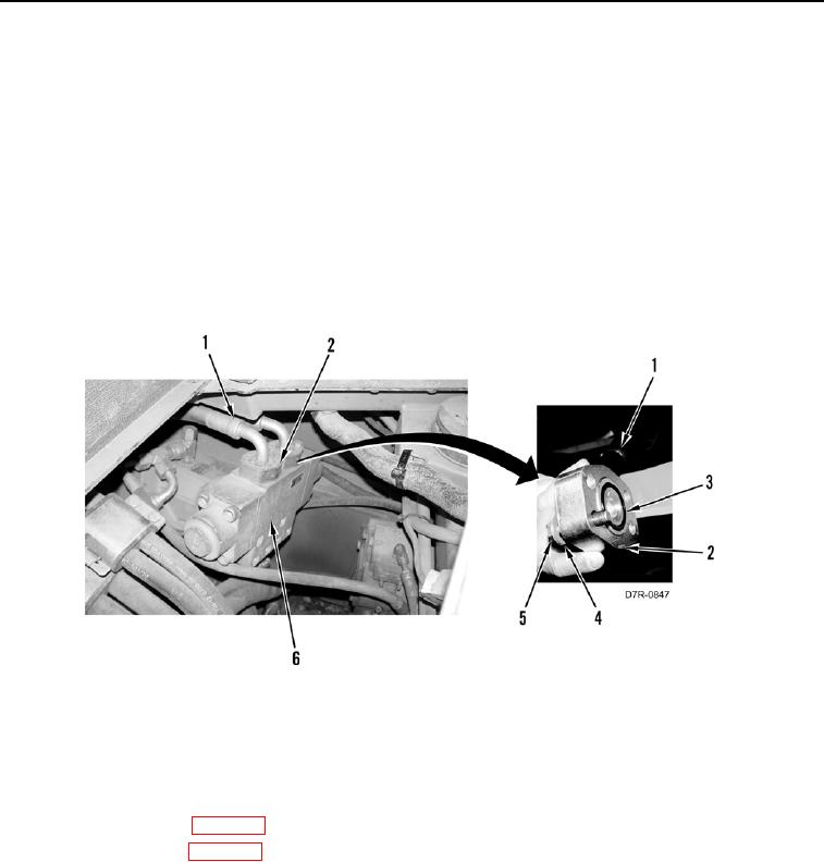
4. Install two new O-rings (Figure 4, Item 3) on hoses (Figure 4, Item 1).
5. Install two hoses (Figure 4, Item 1), two flanges (Figure 4, Item 2), eight washers (Figure 4, Item 4), and bolts
(Figure 4, Item 5) on counterbalance valve (Figure 4, Item 6).
Figure 4. Counterbalance Valve.
0217
END OF TASK
FOLLOW-ON TASKS
000217
1. Fill hydraulic system (WP 0184).
2. Install front floor plate (WP 0230)
3. Install rear floor plate (WP 0231)
4. Verify correct operation of machine (TM 5-2410-241-10).
END OF TASK
END OF WORK PACKAGE