
TM 5-2410-241-23-3
0217
REMOVAL CONTINUED
WARN I N G
Use extreme caution when handling heavy parts. Provide adequate support and use
assistance during procedure. Ensure lifting device used is in good condition and of
suitable load capacity. Keep clear of heavy parts supported only by lifting device. Failure
to follow this warning may cause injury or death to personnel.
N OT E
Counterbalance valve weighs approximately 75 lb (35 kg).
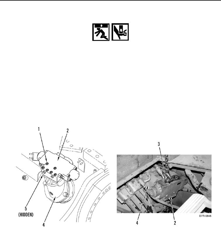
3. Attach bracket link (Figure 2, Item 3) and lifting device on counterbalance valve (Figure 2, Item 2).
4. Using lifting device, remove six bolts (Figure 2, Item 1), counterbalance valve (Figure 2, Item 2), and two O-
rings (Figure 2, Item 5) from motor (Figure 2, Item 4). Discard O-rings
5. Place counterbalance valve (Figure 2, Item 2) on clean work surface.
6. Remove lifting device and bracket link (Figure 2, Item 3) from counterbalance valve (Figure 2, Item 2).
Figure 2. Counterbalance Valve Mounting.
0217
END OF TASK