
TM 5-2410-241-23-3
0265
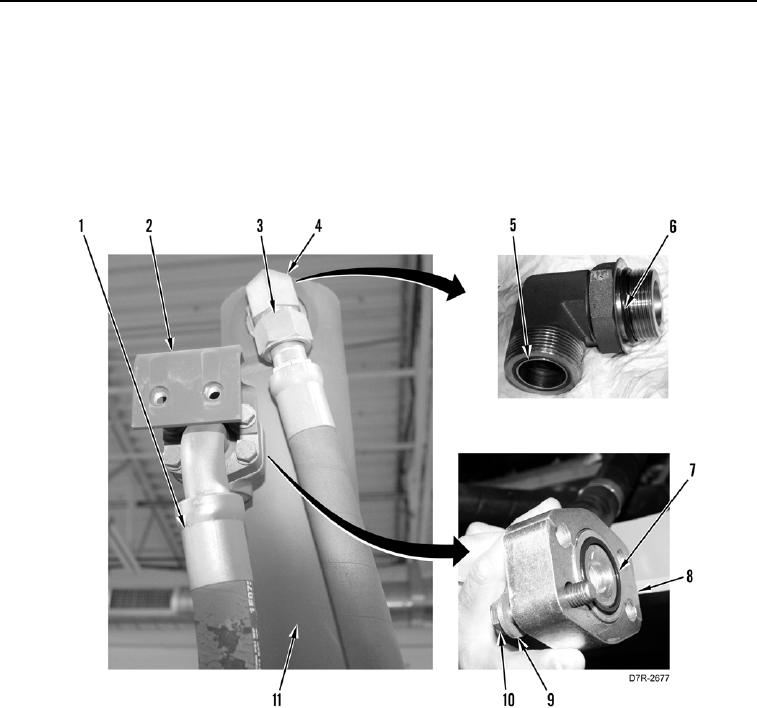
INSTALLATION CONTINUED
3. Install two new O-rings (Figure 6, Items 5 and 6) on elbow (Figure 6, Item 4).
4. Install elbow (Figure 6, Item 4) on lift cylinder (Figure 6, Item 11).
5. Connect hose (Figure 6, Item 3) to elbow (Figure 6, Item 4).
6. Install new O-ring (Figure 6, Item 7) and two flanges (Figure 6, Item 8) on hose (Figure 6, Item 1).
7. Connect hose (Figure 6, Item 1) to lift cylinder (Figure 6, Item 11), and install bracket (Figure 6, Item 2), four
washers (Figure 6, Item 9), and bolts (Figure 6, Item 10).
Figure 6. Upper Hose Connection.
0265