
TM 5-2410-241-23-3
0265
REMOVAL CONTINUED
N OT E
Tag all hoses, tubes, and fittings to aid installation.
Use a container to catch any fluid that maydrain from hoses or system. Dispose of fluid
IAW local policy and ordinances. Ensure all spills are cleaned up.
Note routing of hoses and lines to aid installation.
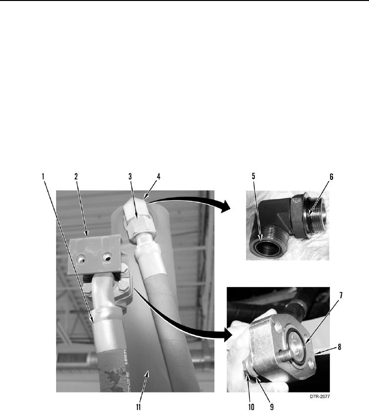
5. Remove four bolts (Figure 3, Item 10), washers (Figure 3, Item 9), bracket (Figure 3, Item 2), and disconnect
hose (Figure 3, Item 1) from lift cylinder (Figure 3, Item 11).
6. Remove two flanges (Figure 3, Item 8) and O-ring (Figure 3, Item 7) from hose (Figure 3, Item 1). Discard O-
ring.
7. Disconnect hose (Figure 3, Item 3) from elbow (Figure 3, Item 4).
8. Remove elbow (Figure 3, Item 4) from lift cylinder (Figure 3, Item 11).
9. Remove and discard two O-rings (Figure 3, Items 5 and 6) from elbow (Figure 3, Item 4).
Figure 3. Upper Hose Connection.
0265