
TM 5-2410-241-23-3
0265
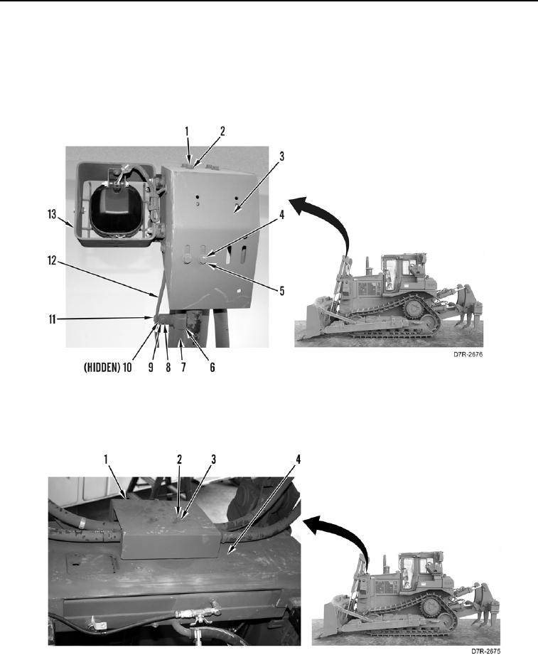
INSTALLATION CONTINUED
8. Install harness (Figure 7, Item 12), cover (Figure 7, Item 3), light (Figure 7, Item 13), four washers (Figure 7,
Item 2), and bolts (Figure 7, Item 1) on machine.
9. Install two washers (Figure 7, Item 5) and bolts (Figure 7, Item 4) on cover (Figure 7, Item 3).
10. Install four flanges (Figure 7, Item 6), two harness clips (Figure 7, Item 11), four washers, (Figure 7, Item 9),
two nuts (Figure 7, Item 10), and bolts (Figure 7, Item 8) on tube (Figure 7, Item 7).
Figure 7. Upper Hose Connection Cover.
0265
11. Install cover (Figure 8, Item 1), three washers (Figure 8, Item 3) and bolts (Figure 8, Item 2) on radiator guard
(Figure 8, Item 4).
Figure 8. Lower Hose Connection Cover.
0265
END OF TASK