
TM 5-2410-241-23-3
0273
REMOVAL CONTINUED
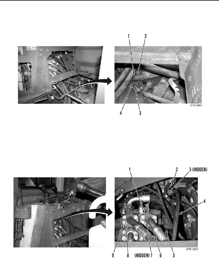
7. Remove bolt (Figure 5, Item 4), washer (Figure 5, Item 3), and retainer clip (Figure 5, Item 1), from two hoses
(Figure 5, Item 2).
Figure 5. Hose Retainer Clip Removal.
0273
8. Disconnect two hoses (Figure 6, Item 4) and O-rings (Figure 6, Item 3) from pilot valve (Figure 6, Item 2).
Remove hoses from machine. Discard O-rings.
9. Remove eight bolts (Figure 6, Item 9), washers (Figure 6, Item 8), four flanges (Figure 6, Item 1), two O-rings
(Figure 6, Item 7), and two hoses (Figure 6, Item 6) from valve bank (Figure 6, Item 5). Remove hoses from
machine. Discard O-rings.
Figure 6. Hose Connections at Valve Bank.
0273