
TM 5-2410-241-23-3
0273
INSTALLATION CONTINUED
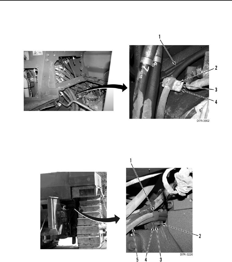
7. Position pump hose (Figure 11, Item 1) and install two retainer clips (Figure 11, Item 4), washer (Figure 11,
Item 3), and bolt (Figure 11, Item 2).
Figure 11. Hose Retainer Clip Installation.
0273
8. Install retainer clip (Figure 12, Item 1) over two hoses (Figure 12, Item 5), and install bolt (Figure 12, Item 2),
washer (Figure 12, Item 4), and nut (Figure 12, Item 3).
Figure 12. Retainer Clip Installation.
0273