• Home
  • Download PDF
  • Order CD-ROM
  • Order in Print
Figure 7. Pump Hose and Retainer.
Figure 9. Hose Connections at Valve Bank.

Field Maintenance Manual 3 D7R Dozer Type I With Winch and Type II With Ripper
Page Navigation
  832    833    834    835    836  837  838    839    840    841    842  
img
.
TM 5-2410-241-23-3
0273
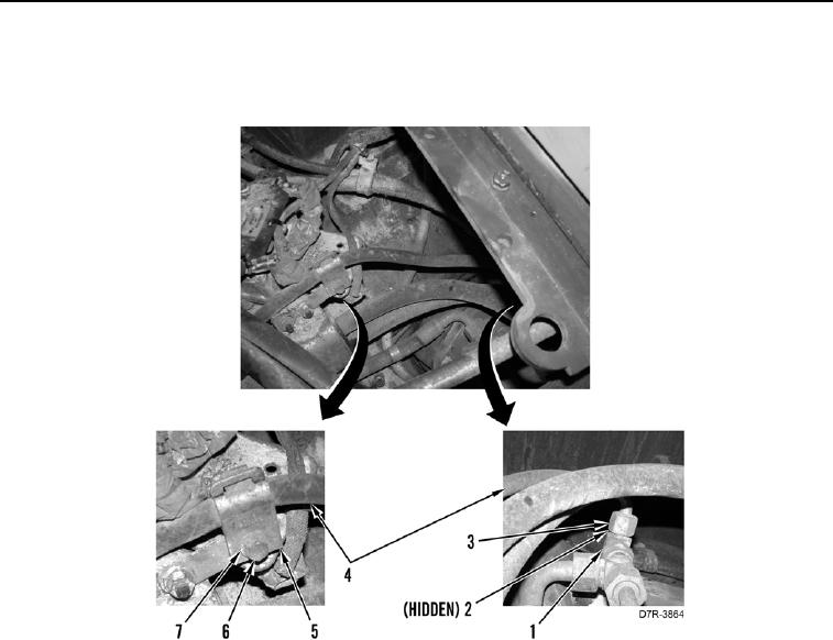
1. Install new O-ring (Figure 8, Item 2) and connect tube nut (Figure 8, Item 3) on tee (Figure 8, Item 1).
2. Position two retainer clips (Figure 8, Item 5) around pump hose (Figure 8, Item 4) and install washer (Figure 8,
Item 7) and bolt (Figure 8, Item 6).
Figure 8. Pump Hose and Retainer Clips.
0273
0273-8


Privacy Statement
Press Release
Contact

© Copyright Integrated Publishing, Inc.. All Rights Reserved.