
TM 5-2410-240-23-1
0031
PISTON PUMP NEUTRAL ADJUSTMENT CONTINUED
12. Perform Mechanical Adjustment, then Hydraulic Adjustment.
Mechanical Adjustment
00031
1. Start and idle engine until engine coolant reaches at least 68F (20C).
2. Using ET enter Transmission Stall Test.
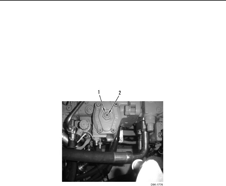
3. Mark initial position of set screw (Figure 27, Item 2), loosen locknut (Figure 27, Item 1), and turn set screw
counterclockwise until pressure increases by 30 psi (207 kPa). Mark this position.
4. Turn set screw back to original position, and turn set screw clockwise until pressure decreases by 30 psi (207
kPa). Mark this position.
5. Position set screw at the midpoint between the two positions in step 3 and step 4.
6. Maintain position of set screw (Figure 27, Item 2) and tighten locknut (Figure 27, Item 1).
Figure 27. Mechanical Adjustment.
0031
7. Stop engine, relieve hydraulic system pressure (WP 0162), and remove pressure hose from left side hydro-
static pump port X1 and X2.
8. Perform steps 17, then proceed with Hydraulic Adjustment.