
TM 5-2410-240-23-2
0050
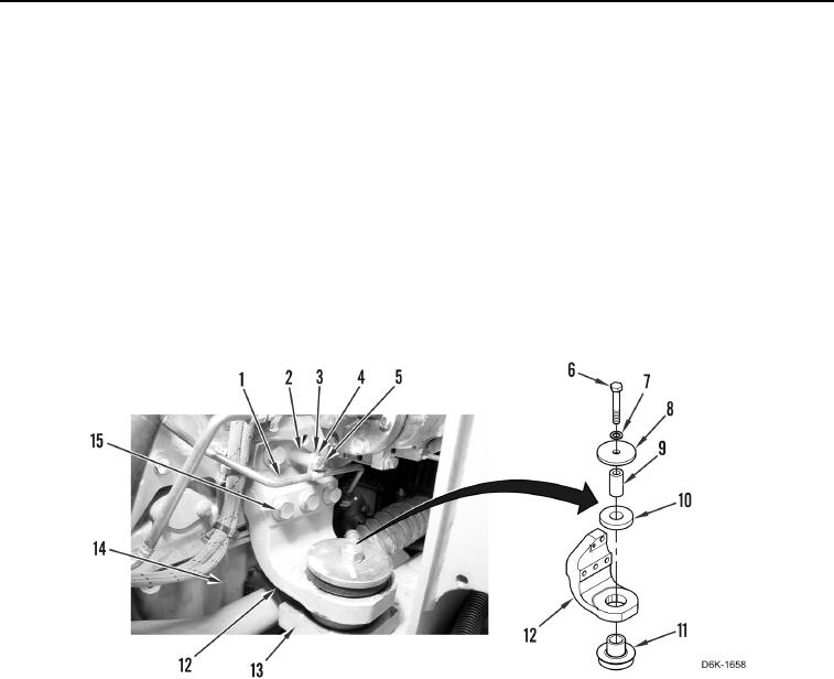
RIGHT FRONT ENGINE MOUNT INSTALLATION
00050
N OT E
Install all bolts before tightening.
1. Install mount (Figure 6, Item 11) and sleeve (Figure 6, Item 9) on machine (Figure 6, Item 13).
2. Install bracket (Figure 6, Item 12) and four bolts (Figure 6, Item 15) on engine (Figure 6, Item 14).
3. Using lifting device and assistance, lower engine (Figure 6, Item 14).
4. Install mount (Figure 6, Item 10), two washers (Figure 6, Items 8 and 7), bolt (Figure 6, Item 6), and support
(Figure 6, Item 12) on machine (Figure 6, Item 13). Torque bolt to 339 44 lb-ft (460 60 Nm).
5. Position tube (Figure 6, Item 1) and install spacer (Figure 6, Item 2), clip (Figure 6, Item 3), washer (Figure 6,
Item 4), and bolt (Figure 6, Item 5) on bracket (Figure 6, Item 12).
6. Remove lifting device from engine (Figure 6, Item 14).
Figure 6. Right Front Engine Mount and Retaining Hardware.
0050
END OF TASK