
TM 5-2410-240-23-2
0050
LEFT FRONT ENGINE MOUNT INSTALLATION
00050
N OT E
Install all bolts before tightening.
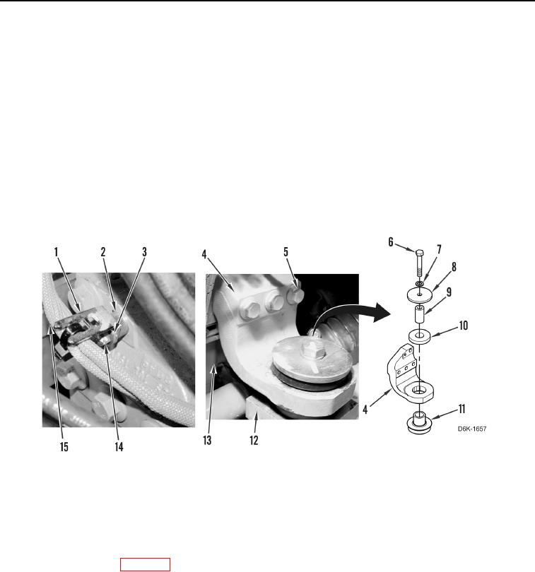
1. Install mount (Figure 7, Item 11) and spacer (Figure 7, Item 9) on machine (Figure 7, Item 12).
2. Install bracket (Figure 7, Item 4) and four bolts (Figure 7, Item 5) on engine (Figure 7, Item 13).
3. Using lifting device and assistance, lower engine (Figure 7, Item 13).
4. Install mount (Figure 7, Item 10), two washers (Figure 7, Items 7 and 8), bolt (Figure 7, Item 6), and bracket
(Figure 7, Item 4) on machine (Figure 7, Item 12).
5. Position wiring harness (Figure 7, Item 15) and install spacer (Figure 7, Item 2), bracket (Figure 7, Item 1),
washer (Figure 7, Item 3), and bolt (Figure 7, Item 14) on bracket (Figure 7, Item 4).
6. Remove lifting device from engine (Figure 7, Item 13).
Figure 7. Left Front Engine Mount and Retaining Hardware.
0050
END OF TASK
FOLLOW-ON TASKS
00050
1. Install hood support (WP 0188).
2. Install bottom guards (WP 0156).
3. Verify correct operation of machine (TM 5-2410-240-10).
END OF TASK
END OF WORK PACKAGE