
TM 5-2410-240-23-2
0051
REMOVAL CONTINUED
N OT E
Note position of coupling assembly to aid installation.
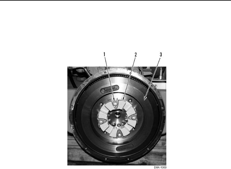
7. Remove four bolts (Figure 4, Item 1) and coupling assembly (Figure 4, Item 2) from flywheel (Figure 4, Item 3).
Figure 4. Flywheel Pump Coupling.
0051
CLEANING AND INSPECTION
00051
Clean and inspect all parts IAW Mechanical General Maintenance Instructions (WP 0282).
END OF TASK
INSTALLATION
00051
N OT E
Install coupling as noted during removal.
1. Install coupling assembly (Figure 4, Item 2) and four bolts (Figure 4, Item 1) on flywheel (Figure 4, Item 3).
Torque bolts to 155 lb-ft (210 Nm).