• Home
  • Download PDF
  • Order CD-ROM
  • Order in Print
Figure 5. Engine Bolts.
ENGINE ASSEMBLY REPLACEMENT - Continued

Field Maintenance Manual 2 D6K Dozer Type I With Winch and Type II With Ripper
Page Navigation
  187    188    189    190    191  192  193    194    195    196    197  
img
.
TM 5-2410-240-23-2
0051
INSTALLATION CONTINUED
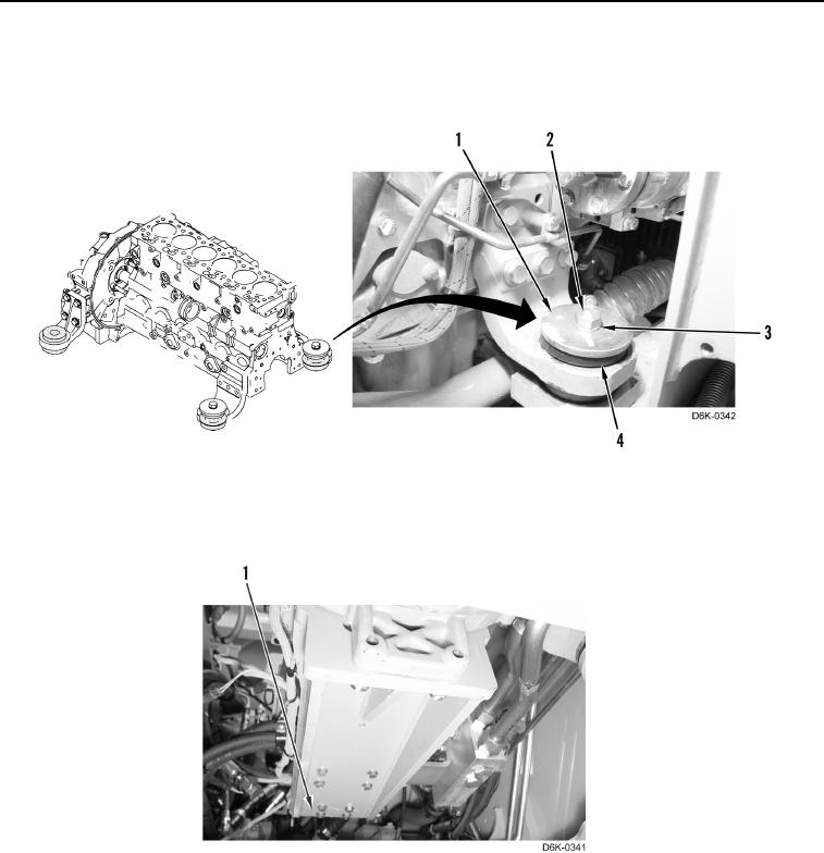
5. Install two mounts (Figure 6, Item 4), two washers (Figure 6, Item 1), two washers (Figure 6, Item 3), and two
bolts (Figure 6, Item 2).
Figure 6. Engine Mount.
0051
6. Remove support from rear of hydrostatic pump assembly (Figure 7, Item 1).
Figure 7. Hydrostatic Pump and Bracket.
0051
7. Remove lifting device from engine.
END OF TASK
0051-7


Privacy Statement
Press Release
Contact

© Copyright Integrated Publishing, Inc.. All Rights Reserved.