
TM 5-2410-240-23-2
0054
REMOVAL CONTINUED
N OT E
Tag and mark wires to aid installation.
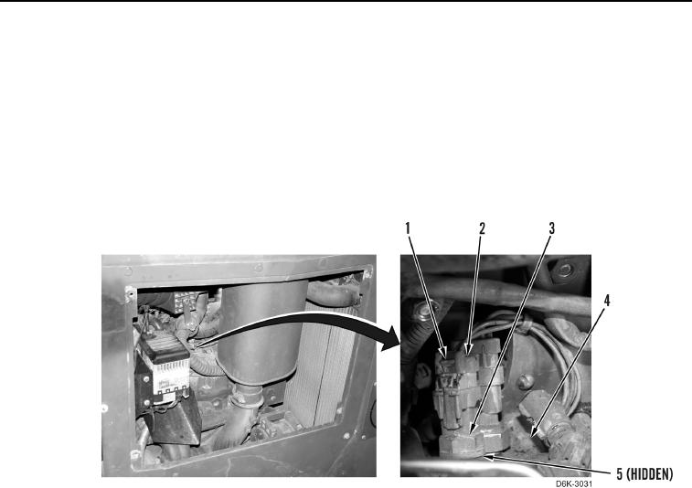
4. Slide lock tab (Figure 3, Item 1) to unlock position and disconnect harness connector (Figure 3, Item 2) from air
intake temperature sensor (Figure 3, Item 3).
5. Remove air intake temperature sensor (Figure 3, Item 3) from engine (Figure 3, Item 4).
6. Remove O-ring (Figure 3, Item 5) from air intake temperature sensor (Figure 3, Item 3). Discard O-ring.
Figure 3. Air Intake Temperature Sensor.
0054
END OF TASK
CLEANING AND INSPECTION
00054
Clean and inspect all components IAW Mechanical General Maintenance Instructions (WP 0282).
END OF TASK