
2
TM 5-2410-240-23-2
FIELD MAINTENANCE
-
FRONT COVER REPLACEMENT
0
087
Removal, Cleaning and Inspection, Installation
INITIAL SETUP
Tools and Special Tools
Equipment Conditions
0
0
Tool Kit, General Mechanic's
Machine parked (TM 5-2410-240-10)
0
(WP 0289, Item 51)
Left engine access panel removed (WP 0184)
0
0
Water pump removed (WP 0083)
Materials/Parts
0
0
Drive belt and tensioner removed (WP 0090)
0
Cleaning compound, solvent, type III
(WP 0290, Item 6)
Drawings Required
0
0
Rag, wiping (WP 0290, Item 21)
TM 5-2410-240-24P, Figure 28
0
0
Gasket
0
Estimated Time to Complete
0
References
0
1.5 Hr
0
WP 0282
0
REMOVAL
00087
N OT E
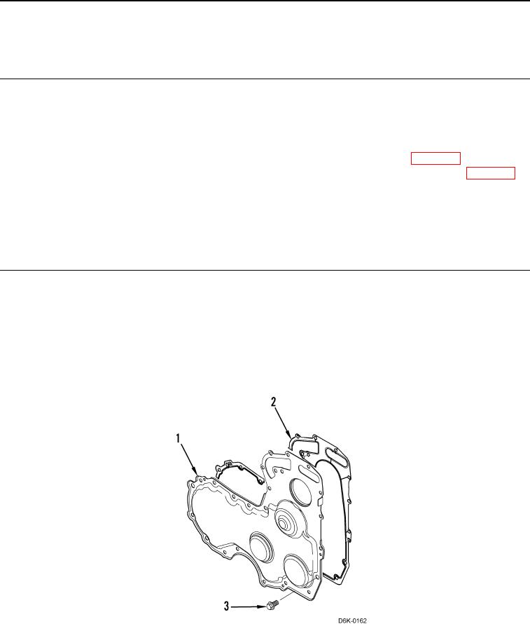
Note length and position of bolts to aid installation.
Remove 15 bolts (Figure 1, Item 3), front cover (Figure 1, Item 1), and gasket (Figure 1, Item 2) from machine.
Discard gasket.
Figure 1. Front Cover Replacement.
0087
END OF TASK