
TM 5-2410-240-23-2
0117
ASSEMBLY
000117
N OT E
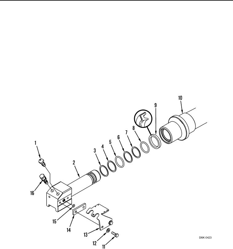
Install O-rings and seals as noted during disassembly.
Lightly grease seals to ease installation of piston.
1. Install lip seal (Figure 4, Item 9) on cylinder (Figure 4, Item 10).
2. Install new backup ring (Figure 4, Item 3), backup ring (Figure 4, Item 4), O-ring (Figure 4, Item 5), backup ring
(Figure 4, Item 6), backup ring (Figure 4, Item 7) and O-ring (Figure 4, Item 8) on piston (Figure 4, Item 2).
3. Install piston (Figure 4, Item 2) on cylinder (Figure 4, Item 10).
4. Install fill valve (Figure 4, Item 1) and relief valve (Figure 3, Item 16) on piston (Figure 4, Item 2).
5. Install new O-ring (Figure 4, Item 15), plate (Figure 4, Item 14), bracket (Figure 4, Item 13), two washers
(Figure 4, Item 12) and bolts (Figure 4, Item 11) on piston (Figure 4, Item 2).
Figure 4. Track Adjuster Piston.
0117