
TM 5-2410-240-23-2
0117
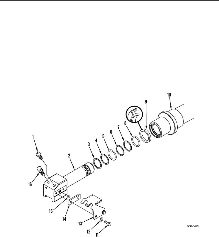
DISASSEMBLY
000117
1. Remove piston (Figure 3, Item 2) from cylinder (Figure 3, Item 10).
2. Remove two bolts (Figure 3, Item 11), washers (Figure 3, Item 12), bracket (Figure 3, Item 13), plate (Figure 3,
Item 14), and O-ring (Figure 3, Item 15) from piston (Figure 3, Item 2). Discard O-ring.
3. Remove relief valve (Figure 3, Item 16) and fill valve (Figure 3, Item 1) from piston (Figure 3, Item 2).
N OT E
Note size and location of O-rings and seals to aid assembly.
4. Remove O-ring (Figure 3, Item 8), backup ring (Figure 3, Item 7), backup ring (Figure 3, Item 6) O-ring
(Figure 3, Item 5), backup ring (Figure 3, Item 4), and backup ring (Figure 3, Item 3) from piston (Figure 3,
Item 2). Discard O-rings and backup rings.
5. Remove lip seal (Figure 3, Item 9) from cylinder (Figure 3, Item 10). Discard lip seal.
Figure 3. Track Adjuster Piston.
0117
END OF TASK
CLEANING AND INSPECTION
000117
Clean and inspect all parts IAW Mechanical General Maintenance Instructions (WP 0282).
END OF TASK