
TM 5-2410-240-23-2
0118
DISASSEMBLY
000118
N OT E
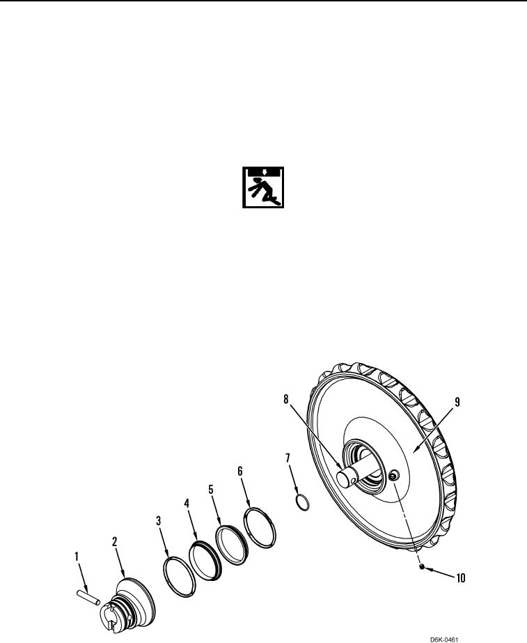
Note size, order, and direction of O-ring seals for installation.
1. Remove dowel (Figure 6, Item 1), bearing (Figure 6, Item 2), toric ring (Figure 6, Item 3), O-ring (Figure 6,
Item 4), O-ring (Figure 6, Item 5), toric ring (Figure 6, Item 6), and O-ring (Figure 6, Item 7) from shaft (Figure
6, Item 8). Discard O-rings.
2. Remove plug (Figure 6, Item 10) from idler (Figure 6, Item 9).
WARN I N G
Use extreme caution when handling heavy parts. Provide adequate support and use
assistance during procedure. Ensure any lifting device used is in good condition and of
suitable load capacity. Keep clear of heavy parts supported only by lifting device. Failure
to follow this warning may result in injury or death to personnel.
N OT E
Idler weighs approximately 320 lb (145 kg).
3. Attach lifting device to idler (Figure 6, Item 9). Using lifting device, remove idler from shaft (Figure 6, Item 8).
Set idler on flat level surface and remove lifting device from idler.
4. Remove dowel (Figure 6, Item 1) and bearing (Figure 6, Item 2) from shaft (Figure 6, Item 8).
Figure 6. Idler.
0118
END OF TASK