
TM 5-2410-240-23-2
0118
INSTALLATION
000118
N OT E
The following procedure is for right yoke and idler assembly. Use the same procedure for
left yoke and idler assembly.
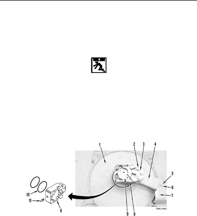
1. Install fitting (Figure 8, Item 11) on each block (Figure 8, Item 8).
2. Install four new O-rings (Figure 8, Item 10) and two blocks (Figure 8, Item 8) on bearing (Figure 8, Item 9).
WARN I N G
Use extreme caution when handling heavy parts. Provide adequate support and use
assistance during procedure. Ensure any lifting device used is in good condition and of
suitable load capacity. Keep clear of heavy parts supported only by lifting device. Failure
to follow this warning may result in injury or death to personnel.
N OT E
Yoke weighs approximately 80 lb (36 kg).
3. With assistance, install the yoke (Figure 8, Item 4), three washers (Figure 8, Item 3), and bolts (Figure 8,
Item 2) on idler (Figure 8, Item 1).
4. Install guard (Figure 8, Item 7), two washers (Figure 8, Item 6), and bolts (Figure 8, Item 5) on yoke (Figure 8,
Item 4).
Figure 8. Yoke Bolts.
0118