
TM 5-2410-240-23-2
0118
INSTALLATION CONTINUED
WARN I N G
Use extreme caution when handling heavy parts. Provide adequate support and use
assistance during procedure. Ensure any lifting device used is in good condition and of
suitable load capacity. Keep clear of heavy parts supported only by lifting device. Failure
to follow this warning may result in injury or death to personnel.
N OT E
Idler and yoke weighs approximately 400 lb (181 kg).
5. Attach lifting device to idler (Figure 9, Item 1) and yoke (Figure 9, Item 6).
6. Using lifting device, flip idler (Figure 9, Item 1) and yoke (Figure 9, Item 6) over. Set idler and yoke on flat level
surface and remove lifting device from idler and yoke.
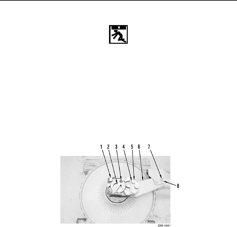
7. Install two washers (Figure 9, Item 8) and bolts (Figure 9, Item 7) on yoke (Figure 9, Item 6).
8. Install three washers (Figure 9, Item 4), bolts (Figure 9, Item 5), key (Figure 9, Item 2), and bolt (Figure 9,
Item 3), on idler (Figure 9, Item 1).
Figure 9. Idler and Yoke Assembly.
0118