
TM 5-2410-240-23-2
0121
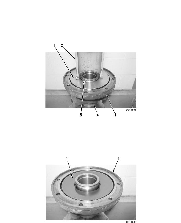
DISASSEMBLY
000121
1. Using a suitable press, sleeve (Figure 4, Item 2), and spacer (Figure 4, Item 4) press down plate (Figure 4,
Item 1).
2. Remove retaining ring (Figure 4, Item 5) from track brake (Figure 4, Item 3).
3. Remove sleeve (Figure 4, Item 2), spacer (Figure 4, Item 4) and plate (Figure 4, Item 1) from track brake
(Figure 4, Item 3).
Figure 4. Retaining Ring.
0121
N OT E
Note position and orientation of disc springs for installation.
4. Remove two disc springs (Figure 5, Item 1) from track brake (Figure 5, Item 2).
Figure 5. Disc Springs.
0121