
TM 5-2410-240-23-2
0123
REMOVAL
000123
WARN I N G
DO NOT disconnect or remove any hydraulic system hoses, tubes, or fittings unless
engine is shut down and hydraulic system pressure has been relieved. Tighten all
connections before applying pressure. Escaping hydraulic fluid under pressure can
penetrate skin.
At operating temperature, hydraulic oil is hot. Allow hydraulic oil to cool before removing
any hydraulic fitting.
Wear protective eye covering and gloves.
Lubricating/hydraulic oils used in performance of maintenance can be very slippery.
Immediately wipe up any spills.
Failure to follow these warnings may result in injury or death to personnel.
N OT E
Tag and mark hose and tube to aid installation.
Use a container to catch any fluid that may drain from hose or system. Dispose of fluid
IAW local policy and ordinances. Ensure all spills are cleaned up.
Cap or plug hose, tube, and open ports.
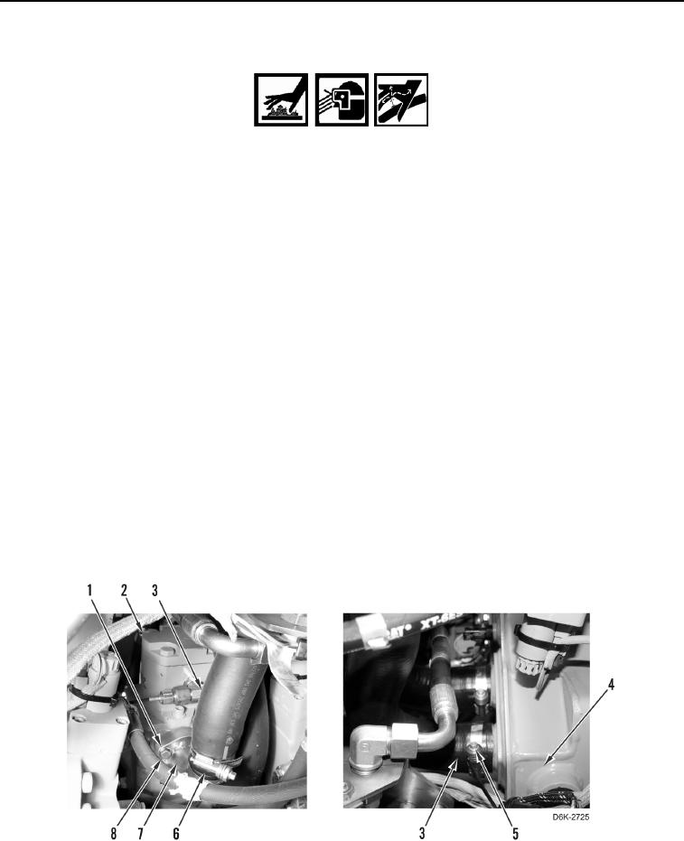
1. Loosen two hose clamps (Figure 1, Items 5 and 6).
2. Remove four bolts (Figure 1, Item 8), washers (Figure 1, Item 1), and tube (Figure 1, Item 7) from hydraulic fan
gear pump (Figure 1, Item 2).
3. Disconnect hose (Figure 1, Item 3) from hydraulic tank (Figure 1, Item 4) and remove hose and tube from
machine.
4. Disconnect hose (Figure 1, Item 3) from tube (Figure 1, Item 7).
Figure 1. Hose, Tube, and Retaining Hardware.
0123