
TM 5-2410-240-23-2
0123
REMOVAL CONTINUED
N OT E
Tag and mark hose, line, and fitting to aid installation.
Note orientation of fitting to aid installation.
Use a container to catch any fluid that may drain from hose, line, or system. Dispose of
fluid IAW local policy and ordinances. Ensure all spills are cleaned up.
Cap or plug hose, line, and fitting.
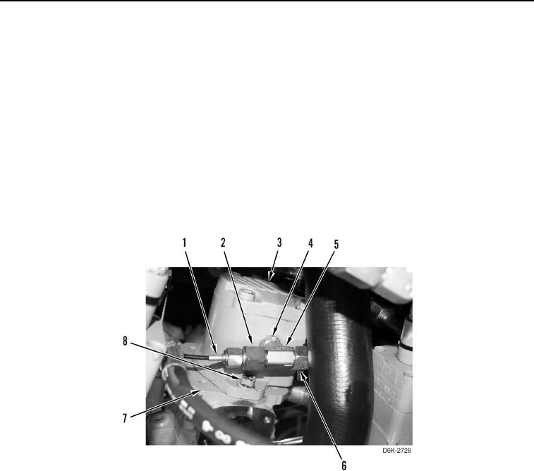
6. Loosen two tube nuts (Figure 3, Item 2) and disconnect line (Figure 3, Item 1) and hose (Figure 3, Item 6) from
fitting (Figure 3, Item 5).
7. Loosen nut (Figure 3, Item 4) and turn fitting (Figure 3, Item 5) 1/4 turn.
8. Remove two bolts (Figure 3, Item 8) and hydraulic fan gear pump (Figure 3, Item 3) from implement pump
(Figure 3, Item 7).
Figure 3. Line, Hose, Fitting, Hydraulic Fan Gear Pump, and Retaining Hardware.
0123