
TM 5-2410-240-23-2
0123
REMOVAL CONTINUED
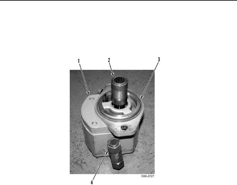
9. Remove coupler (Figure 4, Item 2) from hydraulic fan gear pump (Figure 4, Item 1).
10. Remove O-ring (Figure 4, Item 3) from hydraulic fan gear pump (Figure 4, Item 1). Discard O-ring.
11. Remove fitting (Figure 4, Item 4) from hydraulic fan gear pump (Figure 4, Item 1).
12. Remove three O-rings (Figure 4, Item 3) from fitting (Figure 4, Item 4). Discard O-rings.
Figure 4. O-rings and Fitting on Hydraulic Fan Gear Pump.
0123
END OF TASK
CLEANING AND INSPECTION
000123
Clean and inspect all components IAW Mechanical General Maintenance Instructions (WP 0282).
END OF TASK