
TM 5-2410-240-23-2
0142
REMOVAL CONTINUED
N OT E
Tag and mark electrical connectors to aid installation.
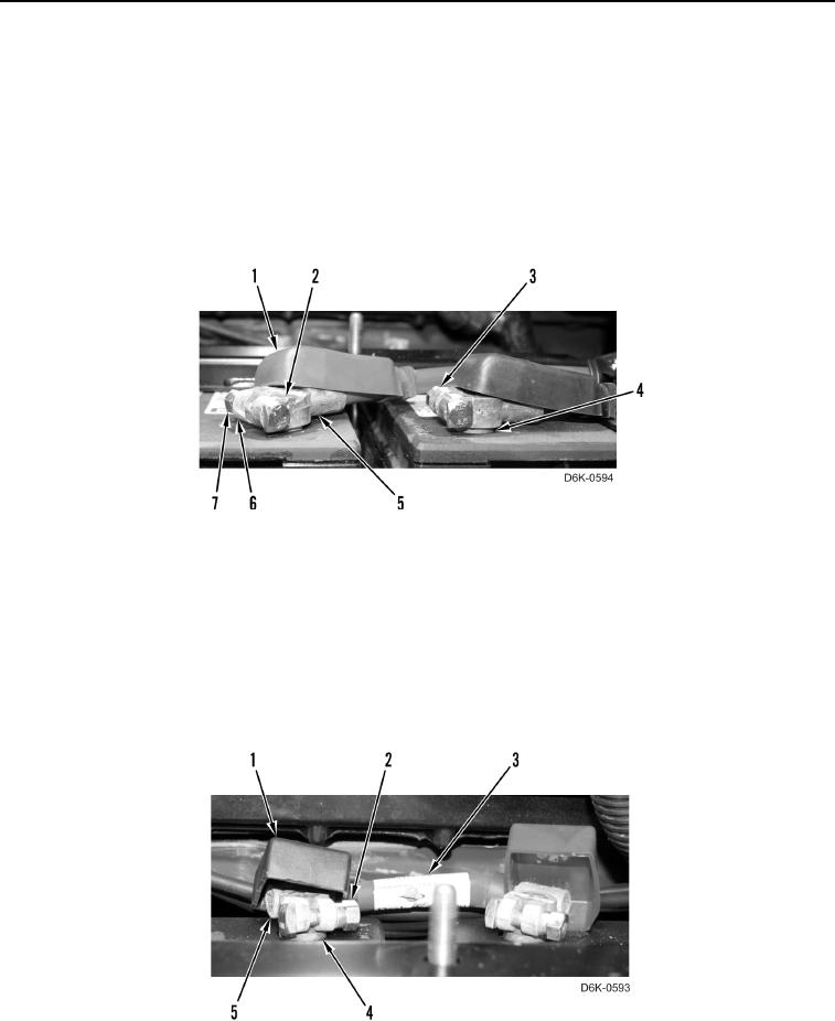
14. Position two terminal covers (Figure 8, Item 1) aside.
15. Loosen two nuts (Figure 8, Item 7) on two terminals (Figure 8, Item 6).
16. Disconnect negative cable (Figure 8, Item 3) from battery negative terminal (Figure 8, Item 4).
17. Disconnect positive cable (Figure 8, Item 5) from battery positive terminal (Figure 8, Item 2).
Figure 8. Battery Cables.
0142
N OT E
Tag and mark electrical connectors to aid installation.
18. Position two terminal covers (Figure 9, Item 1) aside.
19. Loosen two nuts (Figure 9, Item 2) on two terminals (Figure 9, Item 5).
20. Disconnect jumper cable (Figure 9, Item 3) from two battery terminals (Figure 9, Item 4).
Figure 9. Jumper Cable.
0142