
TM 5-2410-240-23-2
0159
HYDRAULIC SYSTEM SUPPLY HOSES AND MANIFOLD INSTALLATION CONTINUED
N OT E
Remove caps or plugs from hose, tube, and open ports.
Install hose and tube as noted during removal.
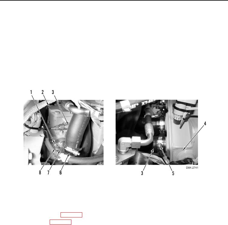
12. Install two clamps (Figure 24, Items 5 and 6) on hose (Figure 24, Item 3).
13. Connect hose (Figure 24, Item 3) to tube (Figure 24, Item 7).
14. Connect hose (Figure 24, Item 3) to hydraulic tank (Figure 24, Item 4).
15. Install tube (Figure 24, Item 7), four washers (Figure 24, Item 1), and bolts (Figure 24, Item 8) on hydraulic fan
gear pump (Figure 24, Item 2).
16. Tighten two clamps (Figure 24, Items 5 and 6).
Figure 24. Tube, Hose, and Retaining Hardware on Hydraulic Fan Gear Pump and Hydraulic Tank.
0159
END OF TASK
FOLLOW-ON TASKS
000159
1. Install rear bottom guards (WP 0156).
2. Fill hydraulic system (WP 0160).
3. Verify correct operation of machine (TM 5-2410-240-10).
END OF TASK
END OF WORK PACKAGE
0159-27/(28 blank)