
TM 5-2410-240-23-3
0179
ASSEMBLY CONTINUED
N OT E
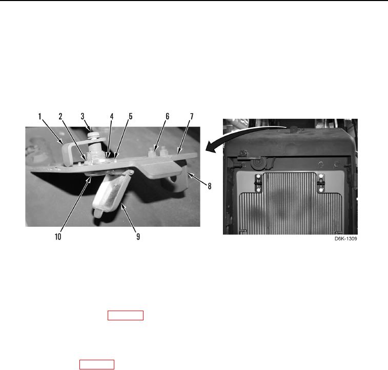
Position latch as noted during removal.
15. Install latch (Figure 7, Item 1) and screw with washer (Figure 7, Item 3) on lock (Figure 7, Item 10).
16. Close cover (Figure 7, Item 9).
17. Close access cover (Figure 7, Item 7).
Figure 7. Access Cover, Latch, Lock, and Retaining Hardware.
0179
END OF TASK
FOLLOW-ON TASKS
000179
1. Install cooling module (WP 0039).
2. Install radiator access door (WP 0181).
3. Install fan support, spider, shroud, and gear motor (WP 0044).
4. Install horn (WP 0139).
5. Stow door shipping brackets (TM 5-2410-240-10).
6. Install radiator grill (WP 0180).
7. Verify correct operation of machine (TM 5-2410-240-10).
END OF TASK
END OF WORK PACKAGE
0179-7/(8 blank)