
TM 5-2410-240-23-3
0197
INSTALLATION CONTINUED
N OT E
Install electrical connectors as noted during removal.
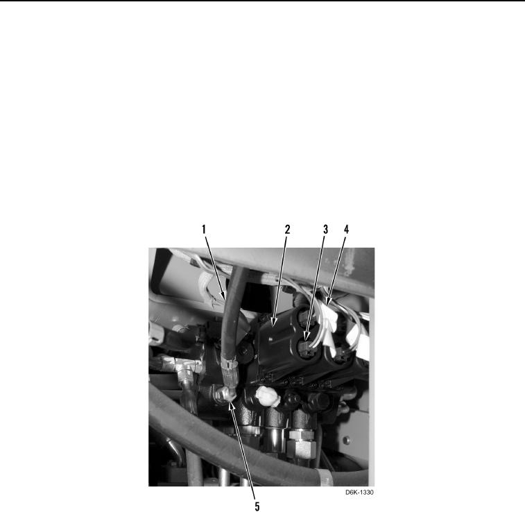
7. Position seven harnesses (Figure 30, Item 4) and connect seven connectors (Figure 30, Item 3) to valve bank
(Figure 30, Item 2).
N OT E
Remove caps from ports for installation.
Install hoses and lines as noted during removal.
8. Connect four hoses (Figure 30, Item 1) to outlet manifold (Figure 30, Item 2) and tighten tube nuts (Figure 30,
Item 5).
Figure 30. Electrical Connectors.
0197