
TM 5-2410-240-23-3
0198
REMOVAL
000198
N OT E
Tag and note hoses to aid installation.
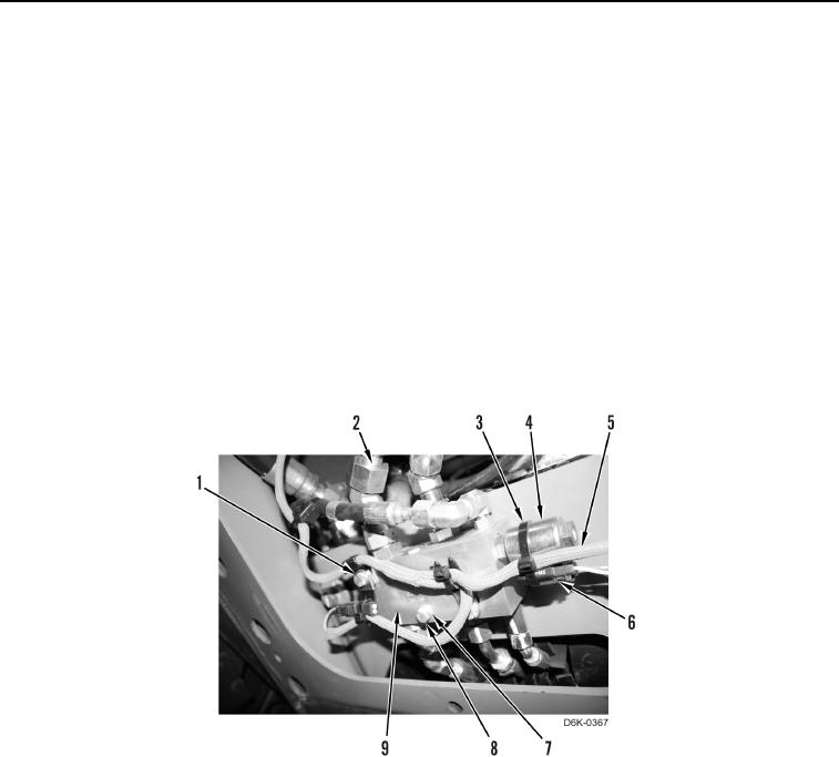
1. Loosen six hose fittings (Figure 1, Item 2) from demand fan manifold (Figure 1, Item 9) and position hose
fittings (Figure 1, Item 2) aside.
N OT E
Tag and note wiring harness to aid installation.
2. Remove tiedown strap (Figure 1, Item 3) from machine and disconnect electrical connector (Figure 1, Item 6)
from solenoid (Figure 1, Item 4). Discard tiedown strap.
3. Remove three bolts (Figure 1, Item 8), washers (Figure 1, Item 7), and clamps (Figure 1, Item 1) from machine
and position wire harness (Figure 1, Item 5) aside.
4. Remove demand fan manifold (Figure 1, Item 9) from machine.
Figure 1. Demand Fan Manifold.
0198