
TM 5-2410-240-23-3
0198
INSTALLATION CONTINUED
N OT E
Install wires, wiring harnesses, and tiedown strap as noted during removal.
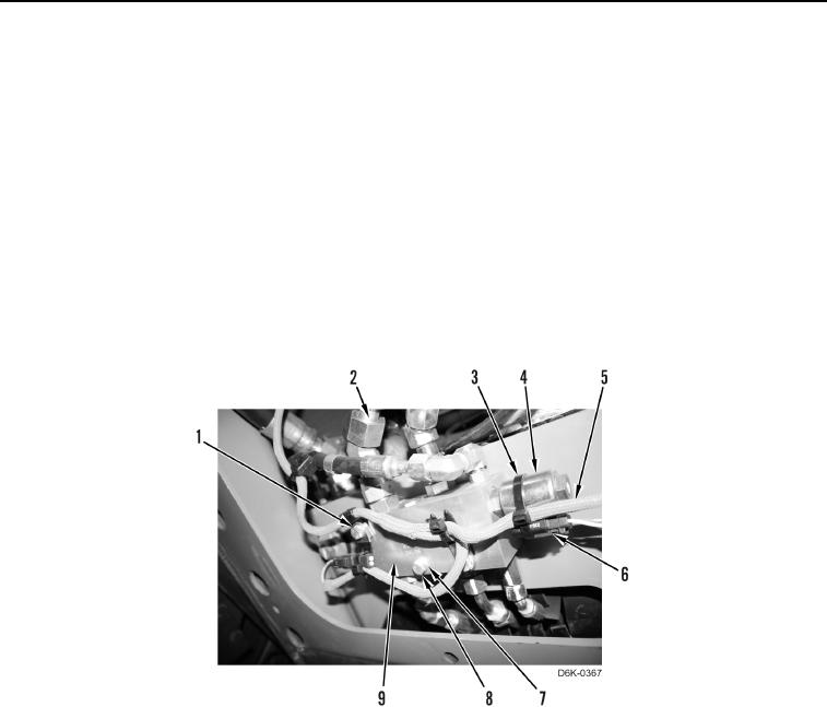
4. Position wire harness (Figure 3, Item 5) and demand fan manifold (Figure 3, Item 9) on machine.
5. Install three clamps (Figure 3, Item 1), washers (Figure 3, Item 7), and bolts (Figure 3, Item 8) on machine.
6. Connect electrical connector (Figure 3, Item 6) to solenoid (Figure 3, Item 4) and install new tiedown strap
(Figure 3, Item 3).
N OT E
Install hose fittings as noted during removal.
7. Remove caps and install six hose fittings (Figure 3, Item 2) on demand fan manifold (Figure 3, Item 9).
Figure 3. Demand Fan Manifold.
0198
END OF TASK
FOLLOW-ON TASKS
000198
1. Check hydraulic fluid (WP 0160).
2. Install front bottom guard (WP 0156).
3. Verify correct operation of machine (TM 5-2410-240-10).
END OF TASK
END OF WORK PACKAGE