
TM 5-2410-240-23-3
0199
REMOVAL CONTINUED
N OT E
Note position of O-rings and seals to aid installation.
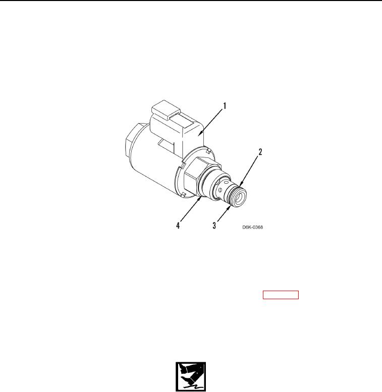
2. Remove O-ring (Figure 2, Item 4), O-ring (Figure 2, Item 3), and backup seal (Figure 2, Item 2) from solenoid
valve (Figure 2, Item 1). Discard O-rings and backup seal.
Figure 2. Solenoid Valve.
0199
END OF TASK
CLEANING AND INSPECTION
000199
Clean and inspect all parts IAW Mechanical General Maintenance Instructions (WP 0282).
END OF TASK
INSTALLATION
000199
WARN I N G
Lubricating/hydraulic oils used in performance of maintenance can be very slippery.
Immediately wipe up any spills. Failure to follow this warning may result in injury to
personnel.
N OT E
Install O-rings and backup seal as noted during removal.
1. Install new O-ring (Figure 2, Item 4), new backup seal (Figure 2, Item 2), and new O-ring (Figure 2, Item 3) on
solenoid valve (Figure 2, Item 1).