
TM 5-2410-240-23-3
0200
REMOVAL CONTINUED
N OT E
Note position of washers to aid installation.
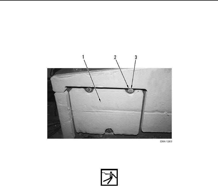
4. Remove three bolts (Figure 2, Item 3), six washers (Figure 2, Item 2), and cover (Figure 2, Item 1) from
machine.
Figure 2. Fuse Panel Side Cover.
0200
WARN I N G
Make sure master battery switch is in OFF position before replacing cables. Failure to
follow this warning may result in injury or death to personnel or damage to equipment.
N OT E
Tag and mark electrical connectors to aid installation.
5. Position two boots (Figure 3, Item 3) aside.
6. Remove two nuts (Figure 3, Item 2), washer (Figure 3, Item 1), and cables (Figure 3, Item 7) from circuit box
(Figure 3, Item 6).
7. Remove two washers (Figure 3, Item 5) and nuts (Figure 3, Item 4) from circuit box (Figure 3, Item 6).