Home
Download PDF
Order CD-ROM
Order in Print
Figure 28. Powertrain Diagnostic Line.
Figure 30. Electrical Connectors.
Field Maintenance Manual 3 D6K Dozer Type I With Winch and Type II With Ripper
Page Navigation
243
244
245
246
247
248
249
250
251
252
253
TM
5-2410-240-23-3
0197
INSTALLATION
CONTINUED
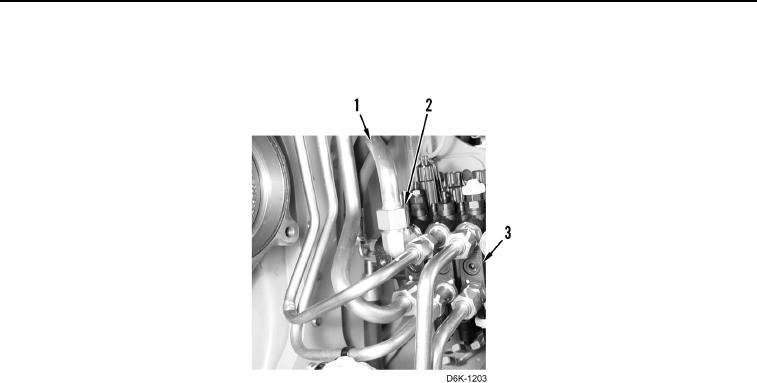
6.
Install
nine
lines
(Figure
29,
Item
1)
and
nine
tube
nuts
(Figure
29,
Item
2) on valve
bank
(Figure
29,
Item
3).
Figure
29.
Valve
Bank
Lines.
0197
0197-25